Lpc2138 miosix board: Difference between revisions
(Created page with " File:Miosix_board.jpeg") |
No edit summary |
||
| Line 1: | Line 1: | ||
The Miosix board was designed in 2009 with the following goals: | |||
* To be used for the development, testing and debugging of the Miosix kernel. | |||
* To be used as a reference implementation of a Miosix based device. | |||
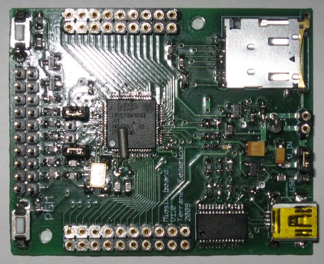
It has mainly an historical purpose now. It is a microcontroller development board based on the LPC2138 microcontroller, supporting filesystem and console I/O thurough an USB to serial adapter. | |||
[[File:Miosix_board.jpeg]] | [[File:Miosix_board.jpeg]] | ||
== Board features == | |||
The board tries to be as general purpose as possible, containing only a basic set of on board peripherals, and breaking out all the microcontroller's unused GPIO on two dual-row headers at the side of the boad. | |||
The board has the following capabilities: | |||
* CPU: LPC2138, based on an ARM7TDMI core, running at 58.9824MHz | |||
* 32KBytes of RAM memory | |||
* 500KBytes of FLASH memory | |||
* Up to 38 GPIO, some of them are capable of ADC, DAC, USART, SPI, I2C. However, some ofthe GPIO have some restriction on its use, and other are multiplexed with other features such as the JTAG debugging. | |||
* A Reset button, and a Pgm button. Pushing both button starts the LPC2138 internal bootloader, which allows device programming with no external hardware. | |||
* An USB connector and an FT232 serial to USB converter. The USB port is used for powering the board, for in system programming through the bootloader and to communicate with a host PC through the console I/O. The default serial speed is 115200baud. | |||
* A microSD slot. The Miosix kernel can read and write Files on the microSD card. | |||
* A JTAG connector for in circuit debugging using OpenOCD. | |||
* Support for low power deep sleep mode, and wakeup from deep sleep either through a time event or an external GPIO event. Power consumption in sleep mode is around 60 microAmper. | |||
* An RTC which is able to handle second, minutes, hour, day, month, year and day of the week. The RTC can wake the board from deep sleep. | |||
* Two 3.3V domains. One is always active and the other is disabled in deep sleep. Both domains can output some current to power external devices. | |||
* An onboard LED, controllable by user code. | |||
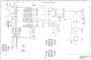
The board schematic is available as open hardware, relesed under a creative commons license, and is available here (png format). | |||
[[File:Miosix board sch.png|thumbnail]] | |||
== Configuring the kernel == | |||
The minimum configuration required is to edit the [[Makefile.inc|miosix/config/Makefile.inc]] file so that the ''OPT_BOARD := lpc2138_miosix_board'' line is uncommented, and the other lines are commented out. Before modifying configuration files it is recomended to do a ''make clean'' (or in the Netbeans IDE, to click on the "Clean project" button) to avoid leaving object files around. After, do a ''make'' to compile. | |||
== Loading code == | |||
The LPC2138 microcontroller has a bootloader programmed by the chip manufacturer that makes downloading the code easy. To enter bootloader mode do this: | |||
on the Miosix board schematic there are two buttons, RESET and PGM. Push and hold down PGM button, push shortly RESET and then release PGM. The microcontroller instead of running user code, will run the bootloader and wait data on the serial port. However, the serial port on the Miosix board is converted to USB for easier interfacing with a PC. | |||
To flash the board using this bootloader the bootloader on Windows you'll need the Flash Magic utility that can be freely downloaded. Once installed, open it and select the main.hex file in your project's top level directory, select as COM port the device name of the USB to serial converter (usually COM4), and lastly use 115200 as baud rate. | |||
On Linux open a terminal in in your project's top level directory and run make program. This is a rule in the makefile that calls the lpc21isp program to download the code to the board. | |||
On Mac OSX things are a little more difficult. Open a terminal in the Hello folder, and run ls -l /dev/tty.*. You need to find the name assigned by the OS to the USB device. It should look like "/dev/tty.usbserial-XXX". Once you find it, note down its name and run sudo ln -s /dev/YOUR_DEVICE_NAME /dev/ttyUSB0. This command will ask your user password. Then do a make program as on Linux. | |||
== Reading printf output == | |||
The LPC2138 board support package redirects printf through the serial port which in turn is converted to USB by the FT232. The baudrate is 115200baud 8N1 format (8 data bit, no parity and one stop bit). | |||
On windows you can use the terminal that comes with Flash Magic (Tools > Terminal), or HyperTerminal. In both cases you need to configure it to use the required baud rate, and no flow control, and the COM port device name (again, usually COM4). | |||
On Linux/Mac open a terminal and type "screen /dev/ttyUSB0 115200" (Note that to quit from screen you need to type "Ctrl-C, \" on Linux and "Ctrl-C, Ctrl-\" on Mac) | |||
If screen is not installed on your Linux distro do a ''sudo apt-get install screen'' | |||
== In circuit debugging == | |||
Before you begin you should note that the Miosix kernel will put the CPU to a low power state when no thread is running. This low power state will usually confuse debuggers and make them lose sync with the CPU. To avoid this you need to edit the miosix/config/miosix_settings.h file and uncomment the #define JTAG_DISABLE_SLEEP line. This will prevent the kernel from putting the CPU in its low power state making debugging possible. | |||
Also, to be able to precisely single-step your code you need to disable compiler optimizations as gdb is incapable of reliably debug an optimized code. The option is in the miosix/config/Makefile.inc file and is the OPT_OPTIMIZATION := -O0 that should be uncommented while the other lines related to the same option should be commented out. | |||
After modifying configuration files it is recomended to do a make clean; make (or in the Netbeans IDE, to click on the "Clean and build project" button) to be sure that changes are applied. | |||
The board has two jumpers above the microcontroller, labeled JTAG_EN. Close those jumpers and connect the JTAG cable of your in circuit debugger to the JTAG header at the top of the board. | |||
On the software side, you need to open two shells. In one do a | |||
sudo openocd -f miosix/arch/arm7_lpc2000/lpc2138_miosix_board/lpc2138_armusbocd.cfg | |||
This will start the OpenOCD program that will connect to the board and listen for GDB connections. | |||
In the second shell type the following commands | |||
<source lang="bash"> | |||
arm-miosix-eabi-gdb main.elf | |||
target remote :3333 | |||
monitor soft_reset_halt | |||
break main | |||
continue | |||
</source> | |||
The first command will start the gdb debugger. The following commands are typed into the gdb console, and tell it to connect to OpenOCD, reset the board and stop at the beginning of main() | |||
From there on, consult a gdb reference on the Internet for information on how to single step code, set breakpoints and inspect variables. | |||
== (Optional) Configuring the Netbeans IDE == | |||
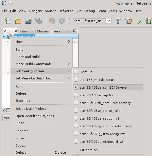
To have a fully working code completion that can also resolve the board-specific symbols, right click on the project, go to Set Configuration and select the right board. | |||
[[File:Netbeans-config.png]] | |||
Revision as of 16:17, 24 August 2015
The Miosix board was designed in 2009 with the following goals:
- To be used for the development, testing and debugging of the Miosix kernel.
- To be used as a reference implementation of a Miosix based device.
It has mainly an historical purpose now. It is a microcontroller development board based on the LPC2138 microcontroller, supporting filesystem and console I/O thurough an USB to serial adapter.
Board features
The board tries to be as general purpose as possible, containing only a basic set of on board peripherals, and breaking out all the microcontroller's unused GPIO on two dual-row headers at the side of the boad. The board has the following capabilities:
- CPU: LPC2138, based on an ARM7TDMI core, running at 58.9824MHz
- 32KBytes of RAM memory
- 500KBytes of FLASH memory
- Up to 38 GPIO, some of them are capable of ADC, DAC, USART, SPI, I2C. However, some ofthe GPIO have some restriction on its use, and other are multiplexed with other features such as the JTAG debugging.
- A Reset button, and a Pgm button. Pushing both button starts the LPC2138 internal bootloader, which allows device programming with no external hardware.
- An USB connector and an FT232 serial to USB converter. The USB port is used for powering the board, for in system programming through the bootloader and to communicate with a host PC through the console I/O. The default serial speed is 115200baud.
- A microSD slot. The Miosix kernel can read and write Files on the microSD card.
- A JTAG connector for in circuit debugging using OpenOCD.
- Support for low power deep sleep mode, and wakeup from deep sleep either through a time event or an external GPIO event. Power consumption in sleep mode is around 60 microAmper.
- An RTC which is able to handle second, minutes, hour, day, month, year and day of the week. The RTC can wake the board from deep sleep.
- Two 3.3V domains. One is always active and the other is disabled in deep sleep. Both domains can output some current to power external devices.
- An onboard LED, controllable by user code.
The board schematic is available as open hardware, relesed under a creative commons license, and is available here (png format).
Configuring the kernel
The minimum configuration required is to edit the miosix/config/Makefile.inc file so that the OPT_BOARD := lpc2138_miosix_board line is uncommented, and the other lines are commented out. Before modifying configuration files it is recomended to do a make clean (or in the Netbeans IDE, to click on the "Clean project" button) to avoid leaving object files around. After, do a make to compile.
Loading code
The LPC2138 microcontroller has a bootloader programmed by the chip manufacturer that makes downloading the code easy. To enter bootloader mode do this: on the Miosix board schematic there are two buttons, RESET and PGM. Push and hold down PGM button, push shortly RESET and then release PGM. The microcontroller instead of running user code, will run the bootloader and wait data on the serial port. However, the serial port on the Miosix board is converted to USB for easier interfacing with a PC.
To flash the board using this bootloader the bootloader on Windows you'll need the Flash Magic utility that can be freely downloaded. Once installed, open it and select the main.hex file in your project's top level directory, select as COM port the device name of the USB to serial converter (usually COM4), and lastly use 115200 as baud rate.
On Linux open a terminal in in your project's top level directory and run make program. This is a rule in the makefile that calls the lpc21isp program to download the code to the board.
On Mac OSX things are a little more difficult. Open a terminal in the Hello folder, and run ls -l /dev/tty.*. You need to find the name assigned by the OS to the USB device. It should look like "/dev/tty.usbserial-XXX". Once you find it, note down its name and run sudo ln -s /dev/YOUR_DEVICE_NAME /dev/ttyUSB0. This command will ask your user password. Then do a make program as on Linux.
Reading printf output
The LPC2138 board support package redirects printf through the serial port which in turn is converted to USB by the FT232. The baudrate is 115200baud 8N1 format (8 data bit, no parity and one stop bit).
On windows you can use the terminal that comes with Flash Magic (Tools > Terminal), or HyperTerminal. In both cases you need to configure it to use the required baud rate, and no flow control, and the COM port device name (again, usually COM4).
On Linux/Mac open a terminal and type "screen /dev/ttyUSB0 115200" (Note that to quit from screen you need to type "Ctrl-C, \" on Linux and "Ctrl-C, Ctrl-\" on Mac) If screen is not installed on your Linux distro do a sudo apt-get install screen
In circuit debugging
Before you begin you should note that the Miosix kernel will put the CPU to a low power state when no thread is running. This low power state will usually confuse debuggers and make them lose sync with the CPU. To avoid this you need to edit the miosix/config/miosix_settings.h file and uncomment the #define JTAG_DISABLE_SLEEP line. This will prevent the kernel from putting the CPU in its low power state making debugging possible. Also, to be able to precisely single-step your code you need to disable compiler optimizations as gdb is incapable of reliably debug an optimized code. The option is in the miosix/config/Makefile.inc file and is the OPT_OPTIMIZATION := -O0 that should be uncommented while the other lines related to the same option should be commented out.
After modifying configuration files it is recomended to do a make clean; make (or in the Netbeans IDE, to click on the "Clean and build project" button) to be sure that changes are applied.
The board has two jumpers above the microcontroller, labeled JTAG_EN. Close those jumpers and connect the JTAG cable of your in circuit debugger to the JTAG header at the top of the board.
On the software side, you need to open two shells. In one do a
sudo openocd -f miosix/arch/arm7_lpc2000/lpc2138_miosix_board/lpc2138_armusbocd.cfg
This will start the OpenOCD program that will connect to the board and listen for GDB connections.
In the second shell type the following commands
arm-miosix-eabi-gdb main.elf
target remote :3333
monitor soft_reset_halt
break main
continue
The first command will start the gdb debugger. The following commands are typed into the gdb console, and tell it to connect to OpenOCD, reset the board and stop at the beginning of main()
From there on, consult a gdb reference on the Internet for information on how to single step code, set breakpoints and inspect variables.
(Optional) Configuring the Netbeans IDE
To have a fully working code completion that can also resolve the board-specific symbols, right click on the project, go to Set Configuration and select the right board.


